Cylinders
Allenair is your single source for dependable, high-quality hydraulic and pneumatic cylinders for industrial applications. When your reputation is on the line, cutting corners is out of the question.
 Allenair designs and builds products right here in the USA that adhere to the highest level of excellence and reliability. Our integrated North American supply chain ensures you will get your product when you need it.
Partnering with us will uphold your hard-earned reputation. Every cylinder we manufacture is durable and built to last, ultimately saving you time and money. Lower quality cylinders may be available from overseas manufacturers, but the cost of failure makes them a costly choice in the long run.
Our friendly, knowledgeable customer service team can help you determine exactly what you need for your project.
Your industrial needs are unique.
Our talented team can create a custom-engineered solution for any application your project requires.
Double Acting Cylinders
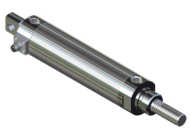
This is Allenair’s largest and most configurable design. Engineered and built to outlast the life of your equipment, our snap ring closure design allows for rebuilding to further extend the life of your cylinder. Using our online configurator, you can generate a 3D model for a Type A, C, or E cylinder to perfectly fit your application. Our large range of bore diameters, rod sizes, and mounting configurations combined with our high-quality materials is a winning combination. Our secure North American supply chain and manufacturing footprint guarantee that you will get your product when you need it.
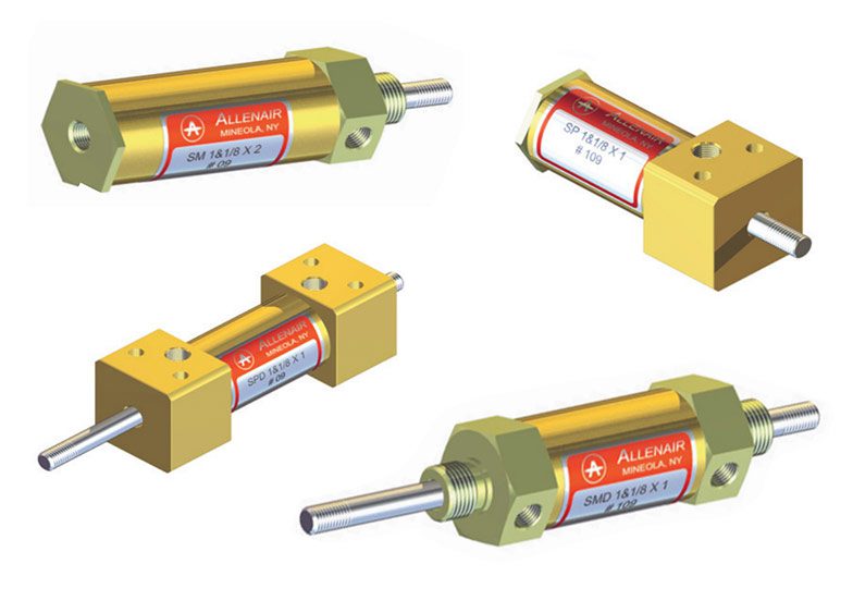
Small Bore Cylinders
Our small bore cylinders come in ½”, ¾”, and 1-1/8” diameter bores up to 14” stroke. These come with brass tubes that are precision honed with a cross-hatch lubricant retaining pattern. The front and rear heads are precision machined and threaded. Seals can easily be replaced if necessary to prolong the life of the cylinder. These can be used for pneumatic and hydraulic pressures up to 150 psi.
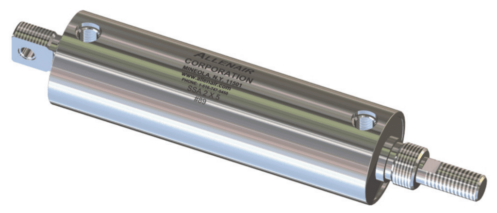
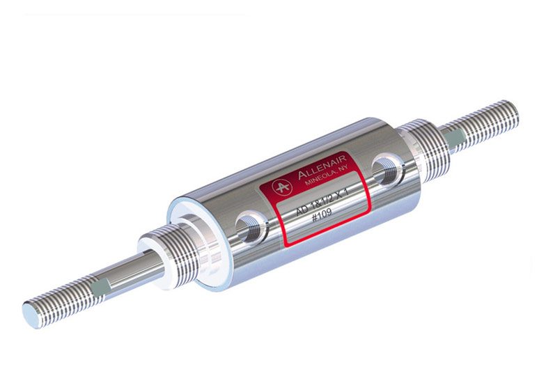
Threaded Construction Stainless Steel Cylinders
Our threaded construction, all stainless steel cylinders are perfect for the food processing industry and any other wash-down required applications. This crevice-free design ensures that all catch points for contamination have been eliminated. They will stand up to repetitive power and chemical wash downs. These can also be rebuilt to help extend the life of the cylinder.
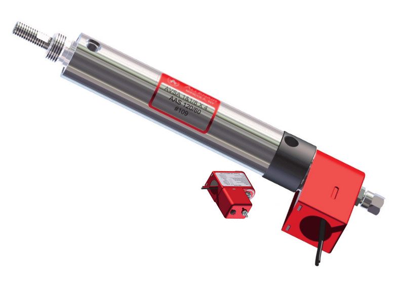
Single and Double Acting Valve-in-Head® Cylinders
Valve-in-Head® cylinders are unique, compact, self-contained units that combine both cylinder and valve into one complete module. This provides the highest level of performance with the quickest valve and cylinder response time and best-in-class flow. Eliminate possible failure points by reducing the number of fittings and tube connections. These cylinders will save on space, time, and cost. The robust design will keep your machine running, maximizing uptime and profits.
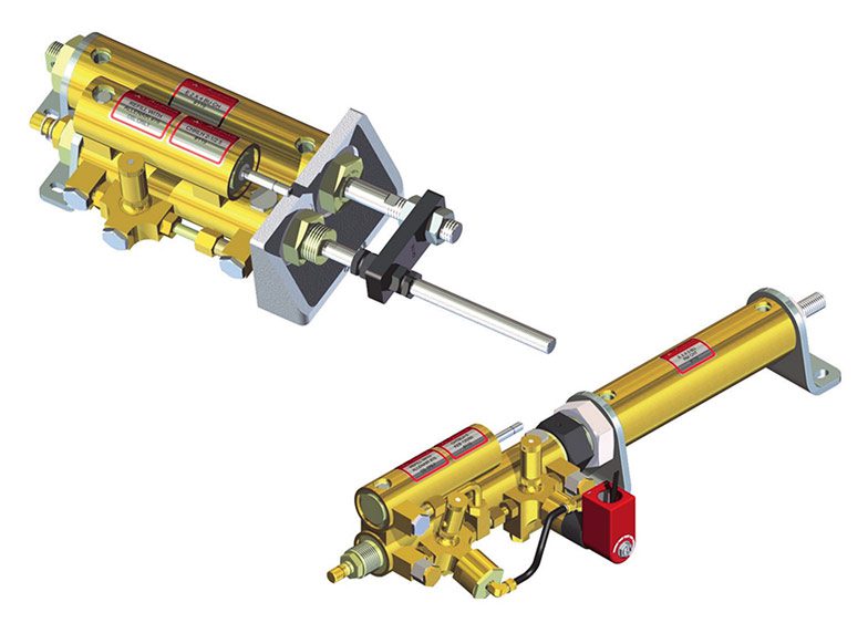
Cyl-Check® Cylinders
When you want the precision control of a hydraulic cylinder, but don’t want to mess with the pump, accumulator, and hoses, consider our Cyl-Check® cylinders. These cylinders are unique in combining the flexibility of a pneumatic cylinder with the control of a hydraulic cylinder in one parallel or tandem mount package. Our self-contained, maintenance-free hydraulic cylinder provides a full range of flow control, anywhere from 1 in/min up to 600 in/min. This, combined with our standard pneumatic cylinder, provides a plug and play unit that only requires standard pneumatic controls and connections. Add a Stop Check to gain the ability to stop the cylinder dead at any or multiple points along the travel, great as an E-stop. Our Skip Check allows for rapid movement in areas where precision control isn’t needed, while still providing the dialed-in hydraulic control where it matters most.
Relying on Allenair for your cylinder needs can help your products perform to your high standards. You have unique industrial needs, and we understand the strict requirements necessary to produce robust and reliable system solutions for your company.